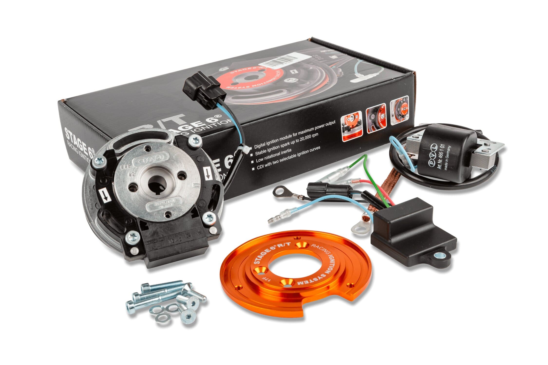
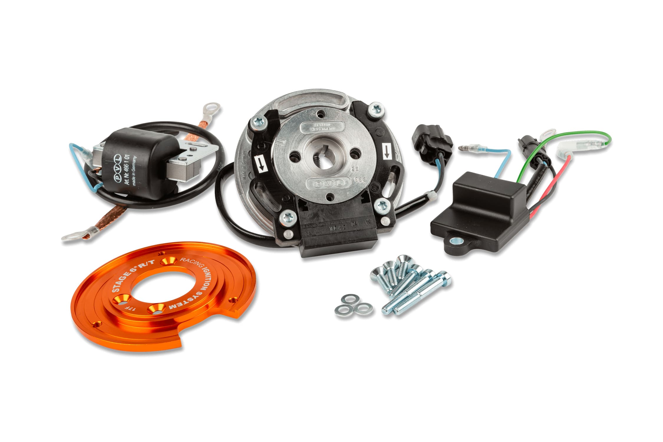
Control unit
- digital ignition with variable advance control unit
- small and light, thanks to SMD assembly technology
High voltage coil
- Start of ignition already at about 400 rpm
- Highly efficient capacitive discharge (CDI)
- constant discharge voltage Stator rotor unit:
Rotor - stator group
- lightweight internal rotor
- low rotational inertia
WIRE CONNECTION FOR MAPPING SELECTION
To select the 2 advance curves, you will need to use a 2-contact switch to connect to the chassis ground.
For a perfect installation, we recommend LEONELLI GEAR SWITCH art. 034.E00. Installation is very simple: first connect the green wire coming out of the control unit to the gear switch; the gear switch has a wire with a ring faston, to be connected to ground on the frame.
-
CURVE 1 : this curve is suitable for drag acceleration races; it can be selected by clicking on the MAP1 button on the LEONELLI gear switch. In this case, a connection of the green wire to the chassis ground is created
-
CURVE 1 : this curve is suitable for track racing; it can be selected by clicking on the MAP2 button on the LEONELLI gear switch. In this case, the connection of the green wire to the frame ground is interrupted
The function of the gear switch is to connect the green wire to the frame ground: if the green wire is connected to ground, CURVE 1 is activated; if the connection is interrupted, CURVE 2 is activated. You can also use this function by using a simple 2-contact button.
CONNECTING WIRE FOR ENGINE SHUTDOWN
The STAGE6 ignition also allows you to turn off and interrupt the engine current. This function can be used by installing a RACING MASS SWITCH. A red wire comes out of the control unit, which must be connected to the mass switch. By removing the button from the vehicle, the red wire is connected to the chassis ground, which immediately turns off the engine.
Mounting on Piaggio LC engine
The weight plate is not supplied, but can be ordered separately using code S6-4514002. Special equipment is required to install the ignition.
The assembly example focuses on a Piaggio 50cc LC engine. The original ignition has been removed from the engine. As a first step, we recommend checking the integrity of the package and its contents, as well as the presence of the necessary equipment. For the simple assembly of the ignition, you only need an M3 and M4 Allen key, at least an 18mm wrench or an 18mm socket with its ratchet. For locking the crankshaft, we recommend a specific tool that acts on the variator side, a piston lock or a pneumatic gun.
For correct ignition timing you need a micrometer, for an even more precise setting we recommend a comparator
The stator support flange is fixed using the 3 M4 screws supplied on the engine crankcase; the screws are fixed using threadlock. Now fit the stator, taking care to place the cable correctly in the appropriate space. Screw in the 3 Allen screws without locking the stator, to allow the timing to be carried out later by rotating it. The original key is also used on this ignition, avoiding movements of the rotor. Now insert the rotor onto the crankshaft, taking care to phase it with the key, then press it down fully. Fix the rotor with the appropriate M12 nut (lock the crankshaft using a specific tool that acts on the variator side, a piston lock or a pneumatic gun). Rotate the engine clockwise until reaching the top dead center and reset the comparator. Now rotate the crankshaft anticlockwise (1 turn of the comparator corresponds to 1mm). The dial indicator will rotate counterclockwise for three complete turns and 0.2 mm, until it reaches the value of 3.2 mm before the top dead center. Note how the reference lines imprinted on the stator and rotor are approaching each other. Keep the crankshaft absolutely still in this position (3.2 mm from the top dead center) and rotate the stator until the two reference lines match. Check the accuracy of the operation several times, finally tightening the stator fixing screws with the aid of threadlocker.
The coil must be fixed to the frame, making sure that the mounting area is unpainted and clean, to ensure good electrical contact. Painted and/or rusted frames near the mounting areas can cause malfunctions and breakages. Try to protect the EEPROM from liquids and vibrations. The black cable, as well as the coil, must have a clean and unpainted contact to the frame. The blue EEPROM cable must be connected to the blue coil cable. The red cable must be connected to the switch. Connecting the latter to ground interrupts the ignition and the engine switches off. If the green cable is brought to ground, the second advance curve (mapping) is activated. The map change must always and strictly be carried out with the engine off, to avoid damaging the EEPROM. Through an optional switch, this process can be facilitated, avoiding annoying connections and disconnections of cables.
Map #1: Green wire not connected to ground – recommended for drag racing
Mapping #2: Green wire connected to ground – recommended for track use
The connection between stator and EEPROM is generated by means of the appropriate plug.
The ground cable must be connected to a ground point on the frame and the engine crankcase, in order to create a bridge between the two.
In general, cables must always be routed in such a way as to avoid possible damage, especially during the movement of the vehicle (heat, rotating masses and engine case flexing). All screws must be secured strictly with appropriate threadlocker. For use in the Stage6 Racing Cup, the rotating elements (rotor) must be covered with a special cover.
For Minarelli engines, the assembly instructions differ in the following points:
· An M5 Allen key is required for assembly.
· The stator support flange must be fixed using 2 M5 x 22mm screws.
· The water pump drive plate must be fixed using 2 M5 x 30mm screws.
Advance variation based on the race:
· Stroke 39.2 - 39.3mm
Connecting rod 80mm 3.20mm
Connecting rod 85mm 3.17mm
Connecting rod 90mm 3.13mm
· Stroke 43.0mm
Connecting rod 80mm 3.57mm
Connecting rod 85mm 3.53mm
Connecting rod 90mm 3.49mm
· Stroke 44.0mm
Connecting rod 80mm 3.68mm
Connecting rod 85mm 3.63mm
Connecting rod 90mm 3.59mm
· Stroke 45.0mm
Connecting rod 80mm 3.78mm
Connecting rod 85mm 3.73mm
Connecting rod 90mm 3.69mm
The Product may be reserved exclusively for competitions in places specially designated for such purposes according to the provisions of the competent sports authorities. We decline all responsibility for improper use.
FOR INFORMATION DO NOT HESITATE TO CONTACT US
Billaricambi staff